I'm planning on making a low power radio transceiver to be used in battery powered sensors. This is my first step in the process. This build is mostly for education purposes and probably wont end up being used for anything, its about going through the motions and learning.
I experimented with simulating a couple different designs before I settled on the final circuit, I started off trying to make a common emitter colpitts but eventually learned that common collector might be better for higher frequencies.
 I buffered the oscillator
stage with a common collector amplifier so there would be enough current
gain to run undisturbed even with a 50 ohm load. I opted to only use an
RF choke for the buffer stage since the oscillator stage won't be
drawing much current and thus shouldn't cause any disturbance to
Vcc.
I buffered the oscillator
stage with a common collector amplifier so there would be enough current
gain to run undisturbed even with a 50 ohm load. I opted to only use an
RF choke for the buffer stage since the oscillator stage won't be
drawing much current and thus shouldn't cause any disturbance to
Vcc.
![]() I aimed to get
a small amount of clipping so I could get a somewhat prominent second
harmonic.
I aimed to get
a small amount of clipping so I could get a somewhat prominent second
harmonic.
 |
 |
|---|
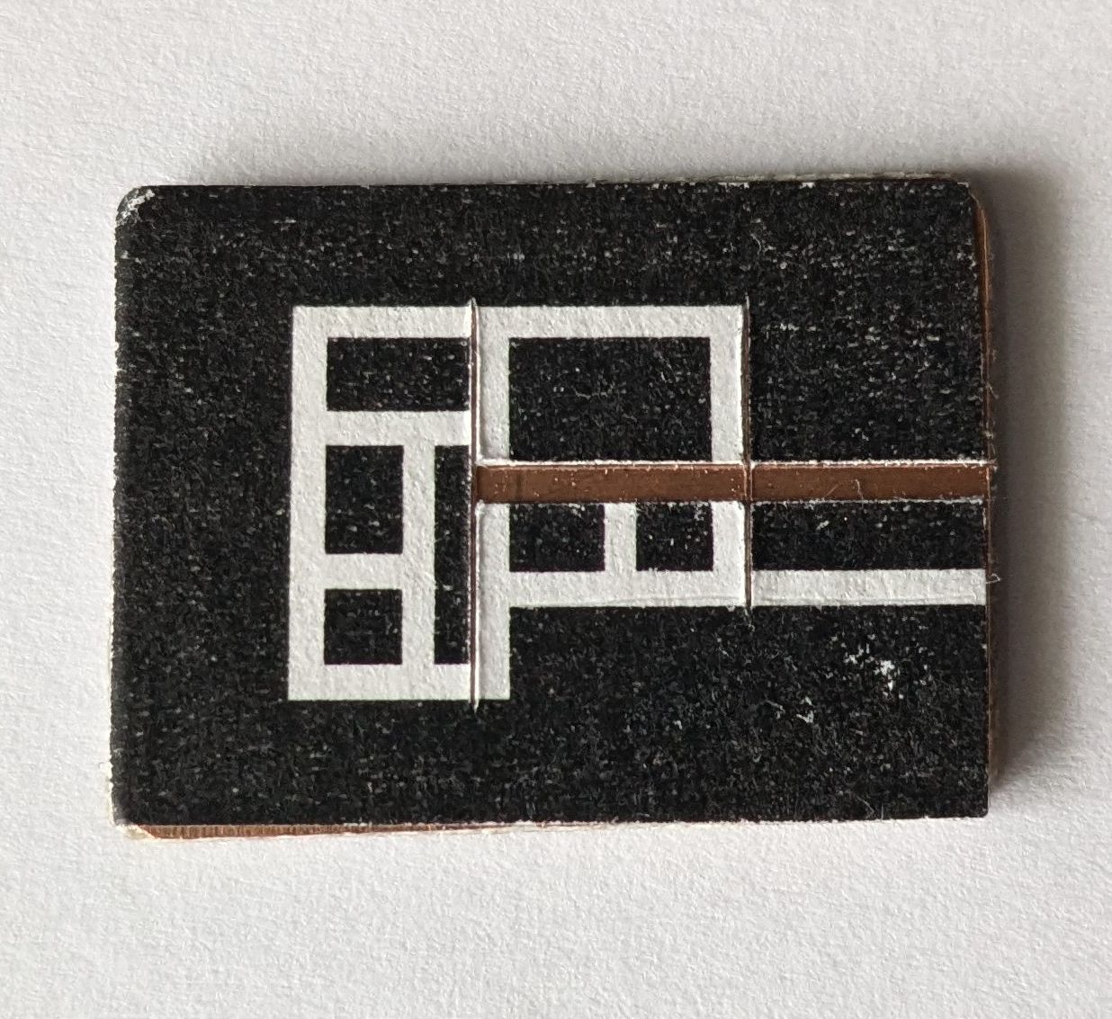
For the layout I started off by drawing up correctly sized prefabs for each of the SMD components I would be using. I then arranged the components in the shape of the circuit and started drawing islands for each node. After a bit of tweaking to make sure the gaps around islands were consistent, I printed it out and checked the scaling to make sure everything would correctly fit. Once I was confident with the layout I moved onto the actual build.
 |
 |
|---|
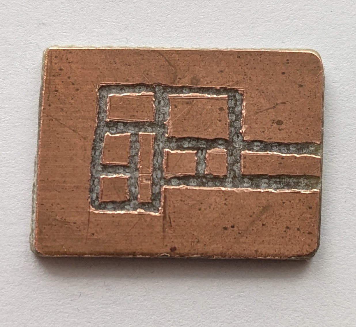
I glued the printout onto a 2 sided copper clad board and initially tried going at it with a box cutter, that didn't end up going so well so I switched to a dremel which did quick work of the copper. Not the cleanest job, but good enough.
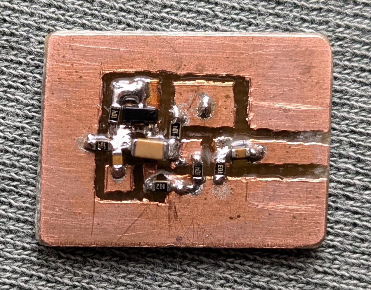 I started off by
soldering all the surface mount components so that any larger components
wouldn't get in the way. I purposefully used a larger capacitor to
couple the oscillator to it's buffer stage so that I could use it to
bridge over the track without needing a two layer board.
I started off by
soldering all the surface mount components so that any larger components
wouldn't get in the way. I purposefully used a larger capacitor to
couple the oscillator to it's buffer stage so that I could use it to
bridge over the track without needing a two layer board.
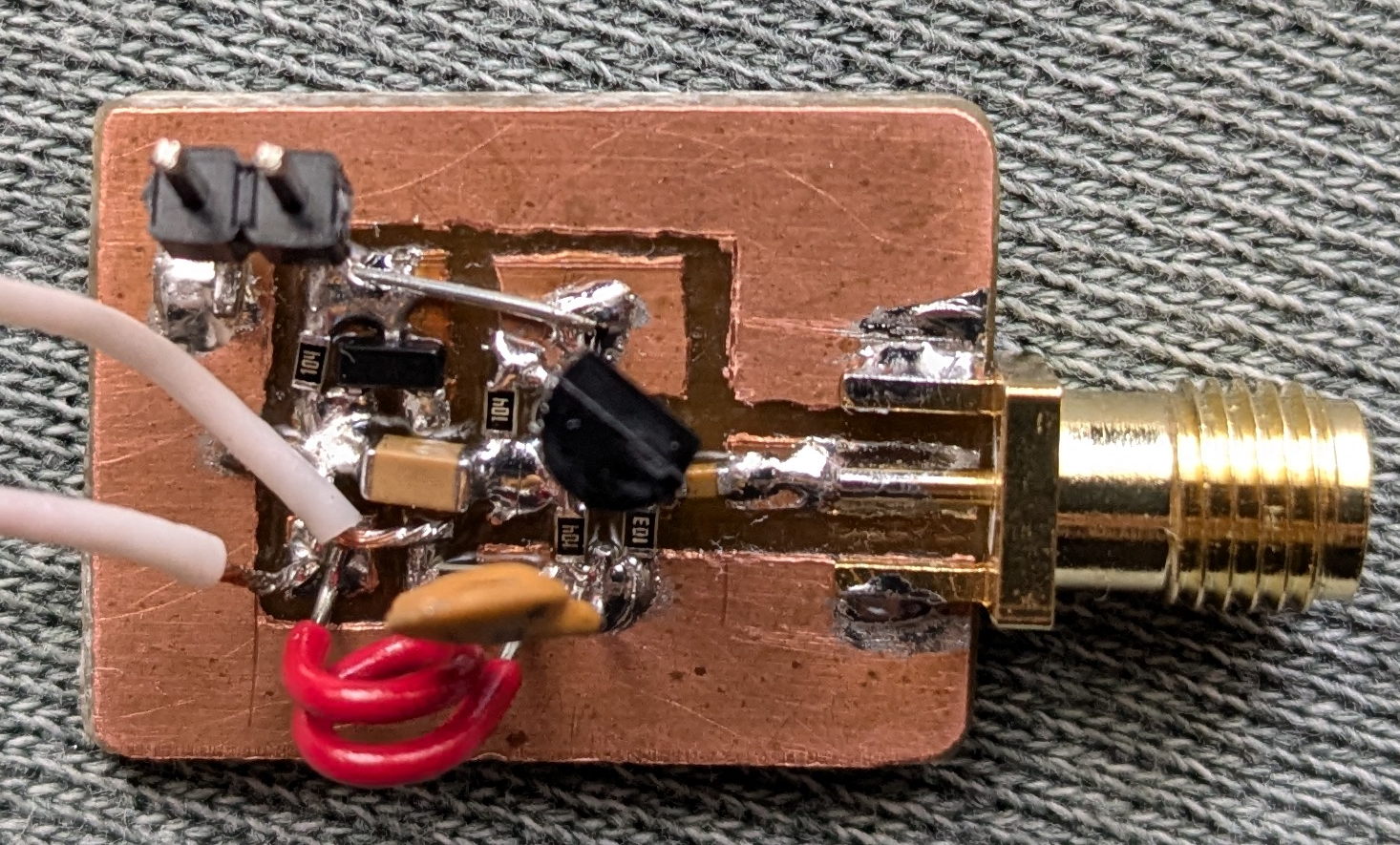
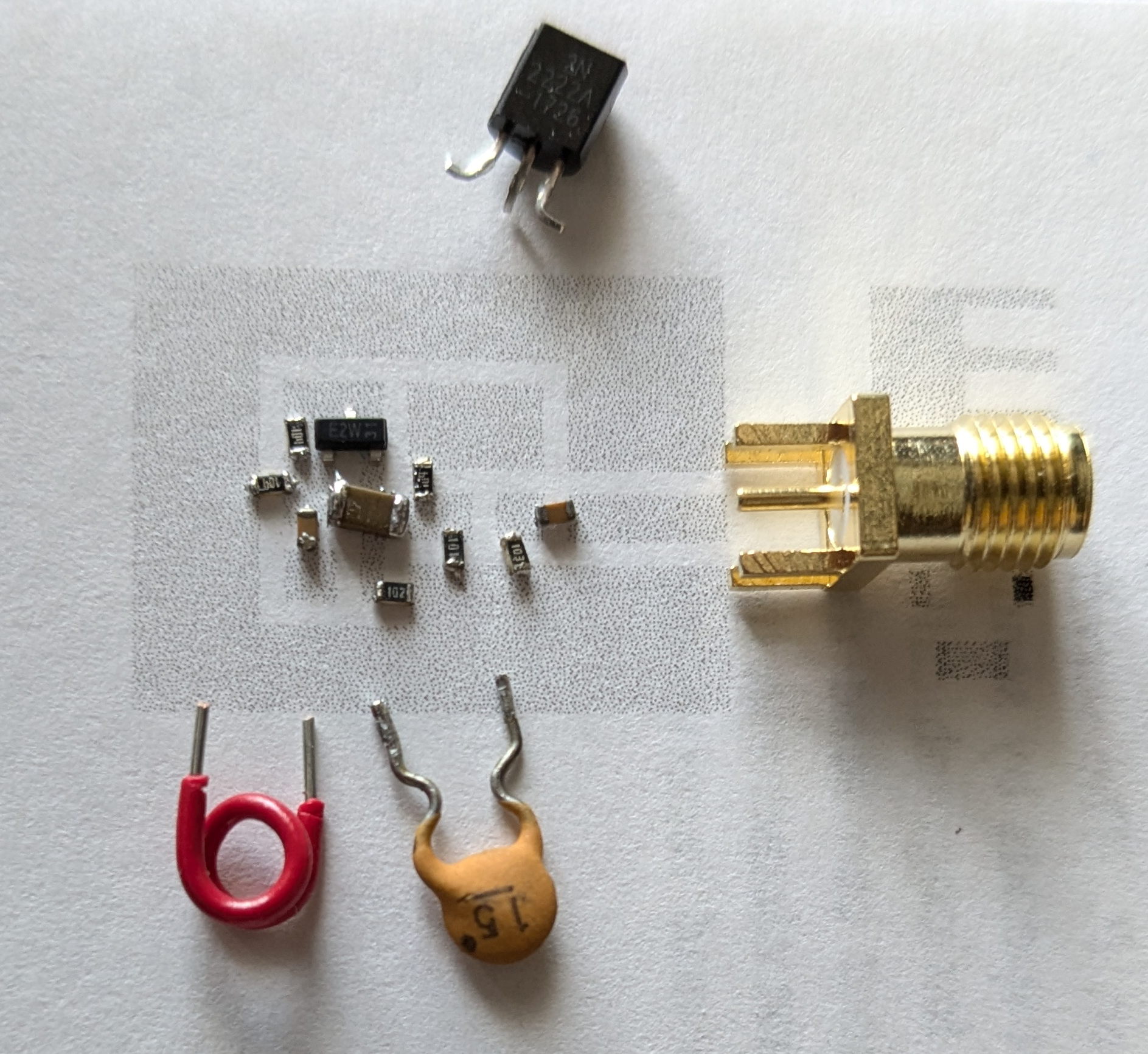
 I then added all the non SMD components. For
the CC (common collector) buffer stage transistor I initially used a
2N2222 since I've a much more plentiful supply of them than BFS17. For
the tank circuit I used a 15pF capactior, an air core inductor I
estimated to be around 10nH, and a crude attempt at a homemade variable
capactior. I opted to leave out the RF choke between the two stages
simply because I was lazy. I just bridged the gap with a wire
instead.
I then added all the non SMD components. For
the CC (common collector) buffer stage transistor I initially used a
2N2222 since I've a much more plentiful supply of them than BFS17. For
the tank circuit I used a 15pF capactior, an air core inductor I
estimated to be around 10nH, and a crude attempt at a homemade variable
capactior. I opted to leave out the RF choke between the two stages
simply because I was lazy. I just bridged the gap with a wire
instead.
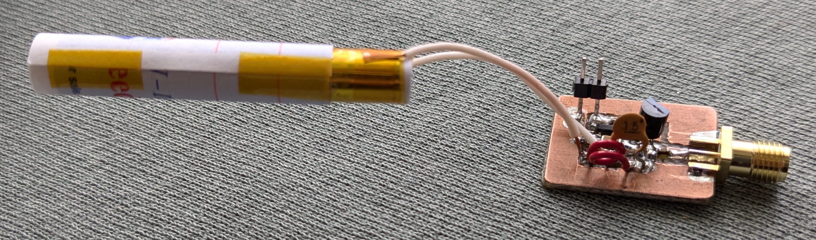
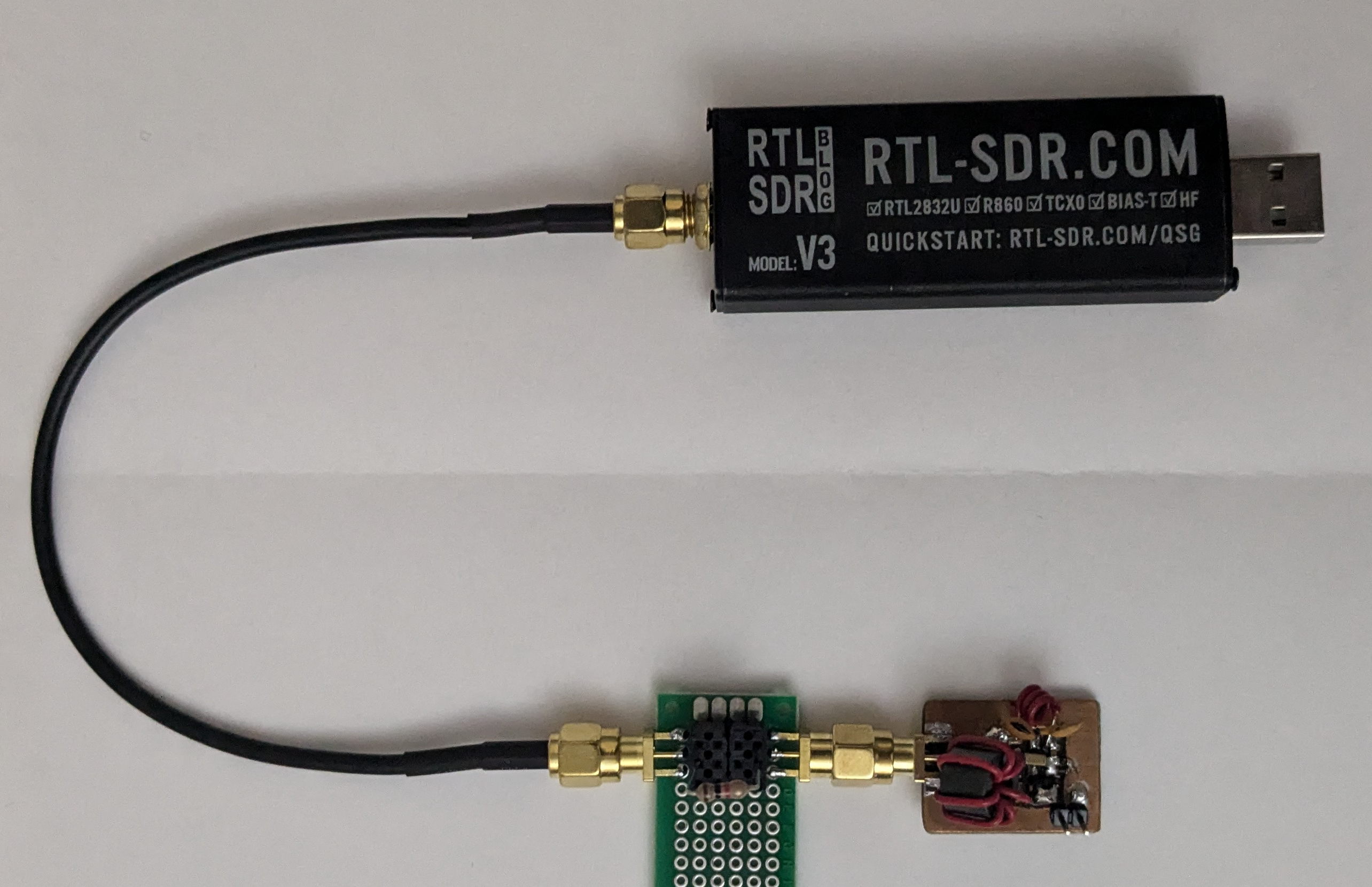
Once assembled, I power it at 5V through a 1kOhm resistor and make sure the current draw is less than the 5mA the resistor would allow (it drew about 1mA which is in line with the simulation). I checked for any shorts and made sure the bias voltages looked fine. The moment of truth came, I start up my spectrum analyzer (an RTLSDR and spektrum) and... Nothing.
What I believe happened here is, since I used the 2N2222 - which isn't rated to work above 300MHz - for the buffer stage, it was putting too heavy a load on the oscillator and damping out any oscillations.
Before I switched out the transistor I swapped out the variable capacitor for a static 47pF capacitor. Still no dice, I probably could have kept the variable cap but I ended up going another less finicky route to dial in the frequency.
 With the 2N2222 swapped for a
faster switching BFS17 It worked! But as expected, at the wrong
frequency. By looking at the frequency I could estimate the value of my
inductor; Assuming the capacitors are perfect and no parasitics. I
calculated an inductance of 26.2nH which is pretty far off from what I
thought it would be.
With the 2N2222 swapped for a
faster switching BFS17 It worked! But as expected, at the wrong
frequency. By looking at the frequency I could estimate the value of my
inductor; Assuming the capacitors are perfect and no parasitics. I
calculated an inductance of 26.2nH which is pretty far off from what I
thought it would be.
 After dealing with stability
issues for an hour I finally caved and put in the RF choke like I was
supposed to do to begin with. This immediately resulted in a much
cleaner and more stable signal - I could've saved myself an hour if i'd
just put it in to begin with.
After dealing with stability
issues for an hour I finally caved and put in the RF choke like I was
supposed to do to begin with. This immediately resulted in a much
cleaner and more stable signal - I could've saved myself an hour if i'd
just put it in to begin with.
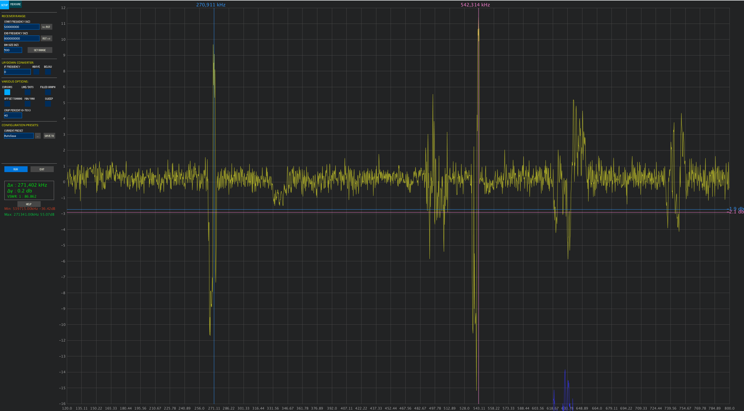
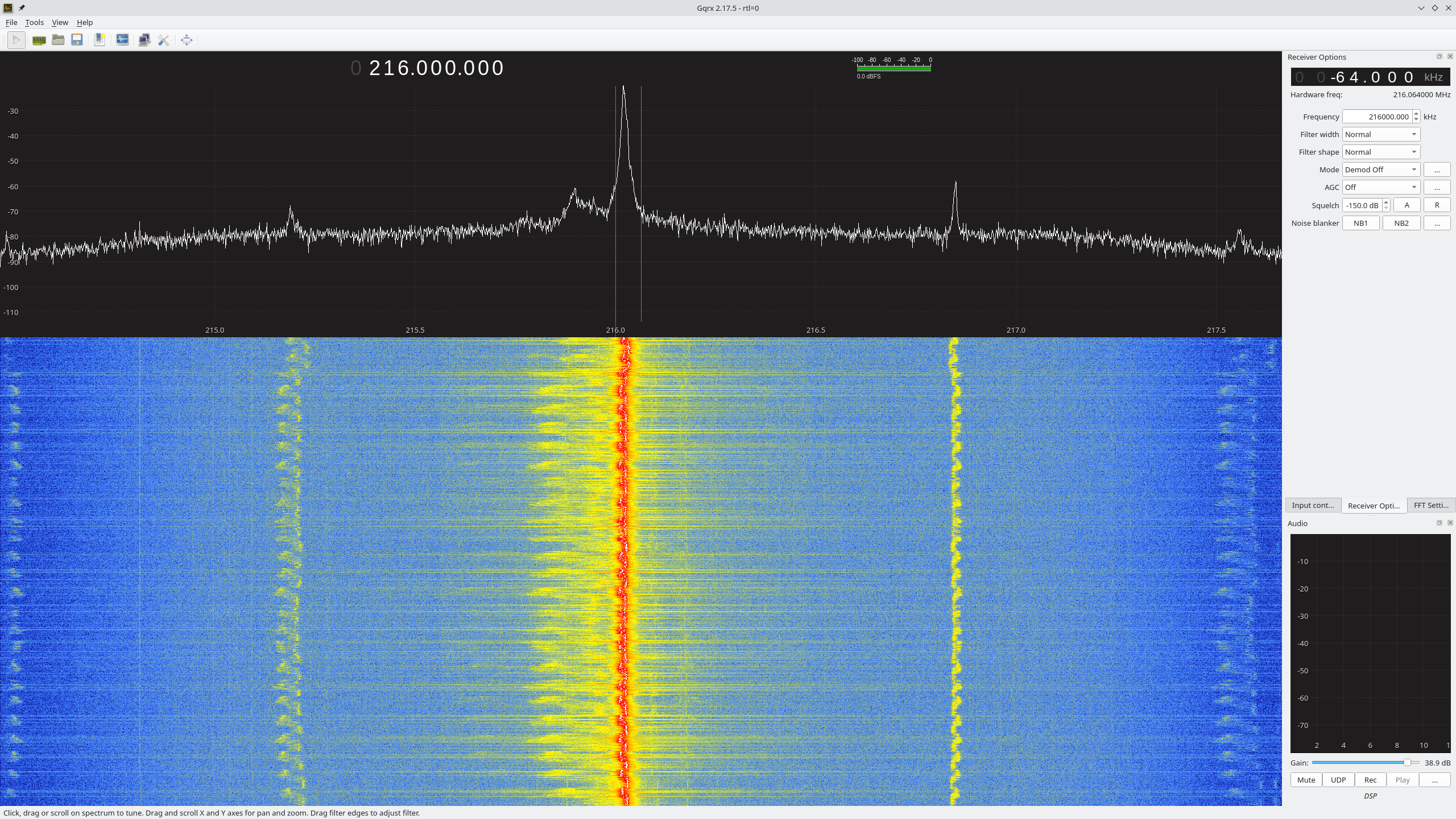
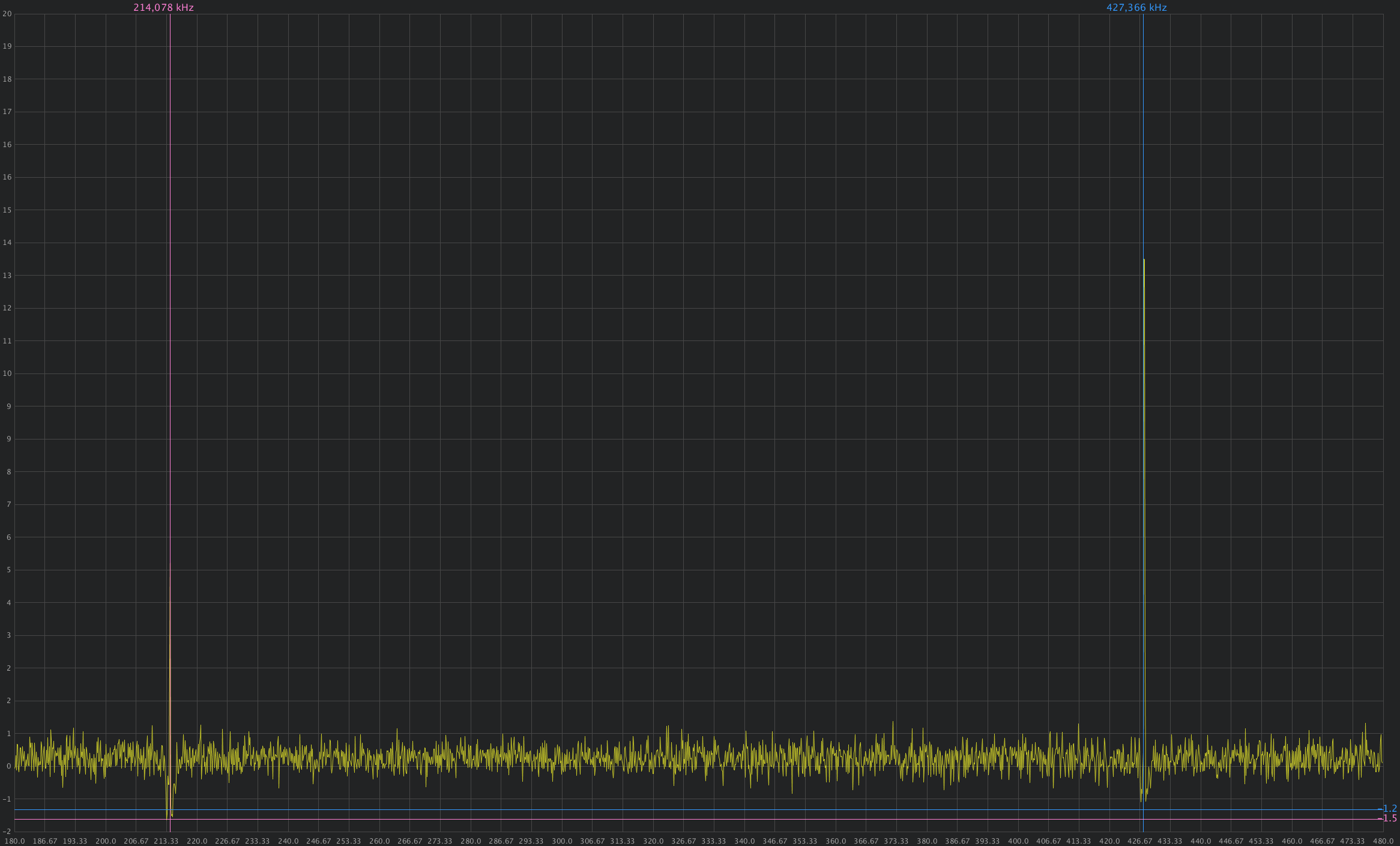
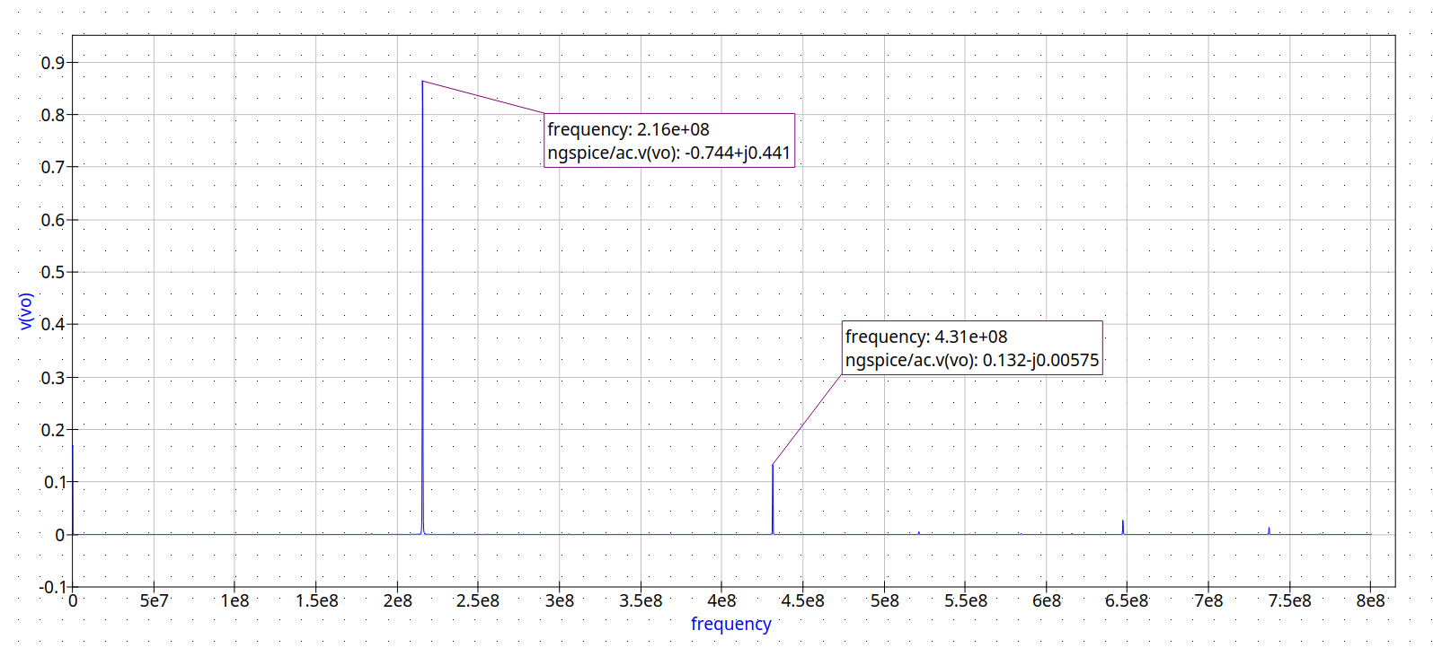 From the simulation I
knew there would be a bit of clipping causing a visible second harmonic
but what I wasn't expecting was for said harmonic to be about as strong
as the fundamental. Note: It probably isn't really as strong as the
fundamental but looking at signal strength using a RTLSDR shows it as
about the same and that's the only tool I have that is able to measure
signal strength.
From the simulation I
knew there would be a bit of clipping causing a visible second harmonic
but what I wasn't expecting was for said harmonic to be about as strong
as the fundamental. Note: It probably isn't really as strong as the
fundamental but looking at signal strength using a RTLSDR shows it as
about the same and that's the only tool I have that is able to measure
signal strength.
It was interesting to see just how sensitive the frequency is to my hand or other conductive objects moving near it.
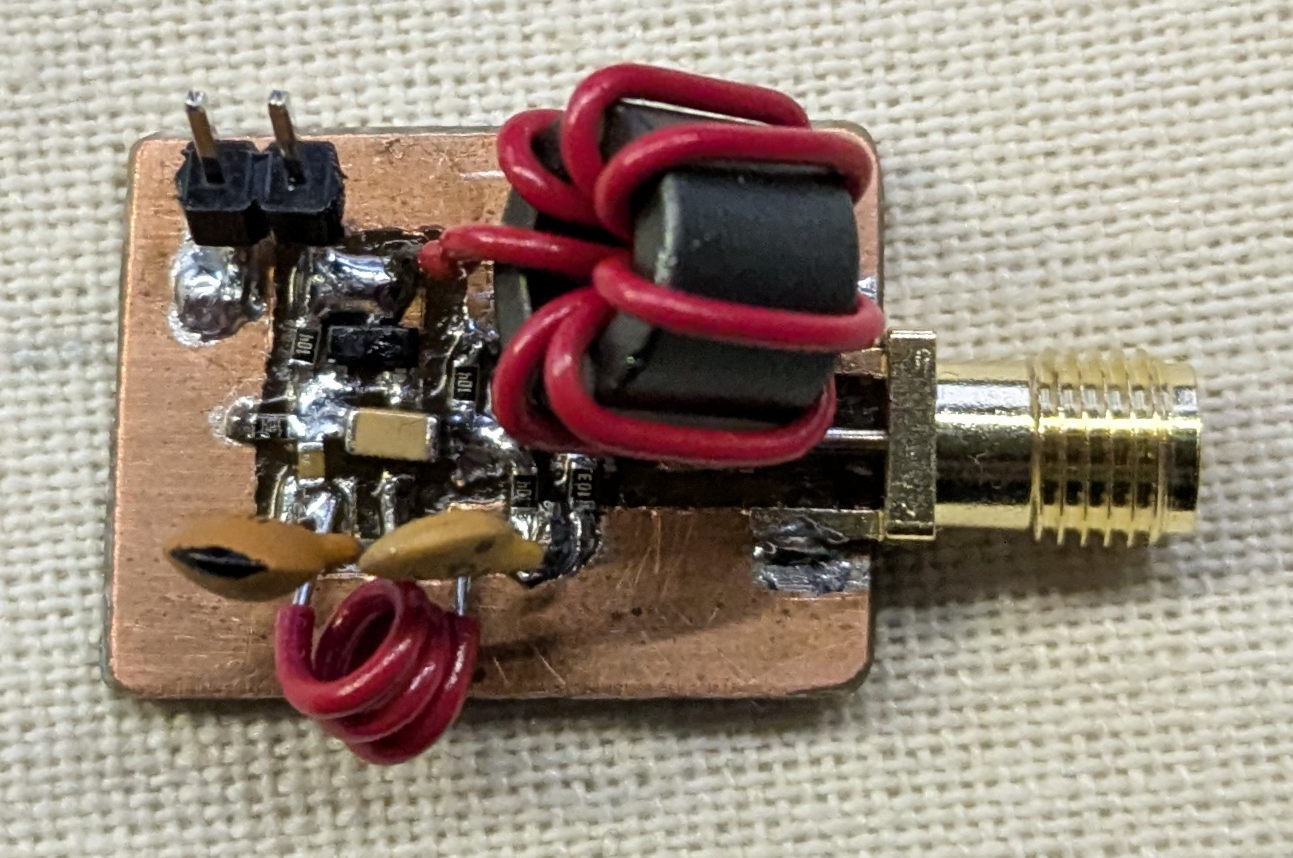
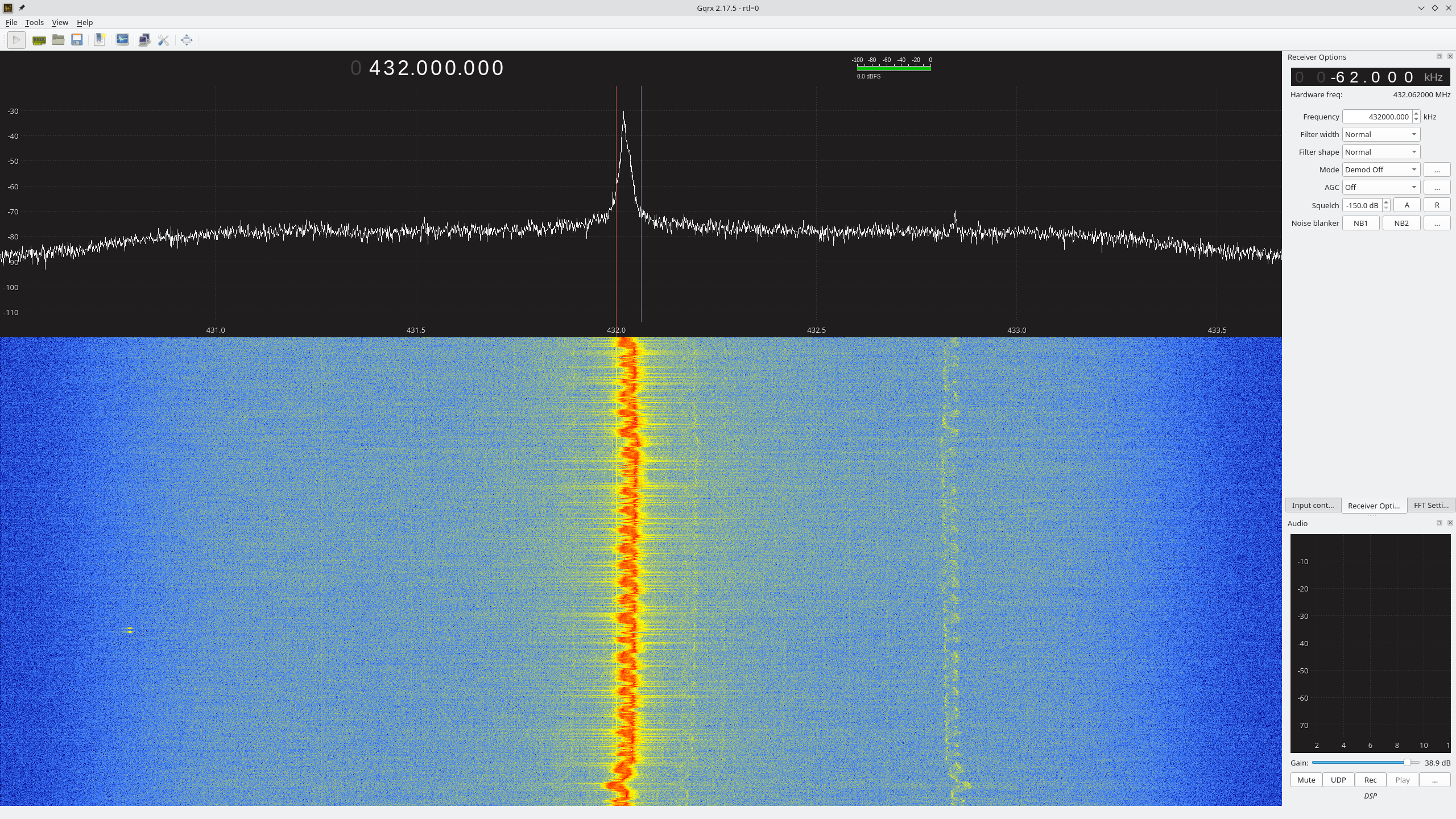
Because of the strength of the second harmonic I had the idea to bring it down to 433MHz instead of bringing the fundamental up. Bringing it down ends up being easier since I can use a bigger value for the inductor and keep the capacitors the same size.
To dial in the frequency I used the inductor. I calculated that I would need 3 turns to bring the frequency down slightly lower than 433MHz. I then stretched out the inductor - lowering its inductance and increasing the resonant frequency - until it resonated at 433MHz.
 All of this testing was done
with no load and the RTLSDR sensing nearby with an antenna. So as you
would expect, the moment I put a 50 Ohm load on it, it stopped
oscillating. I played around with putting 100 and 1k Ohm resistors in
series to see what it would take to get it to oscillate, it oscillated
with 1k but not with 100. This should be fine since i'm not looking to
be making a high power transmitter anyway.
All of this testing was done
with no load and the RTLSDR sensing nearby with an antenna. So as you
would expect, the moment I put a 50 Ohm load on it, it stopped
oscillating. I played around with putting 100 and 1k Ohm resistors in
series to see what it would take to get it to oscillate, it oscillated
with 1k but not with 100. This should be fine since i'm not looking to
be making a high power transmitter anyway.
With the oscillator stable and working, I decided to test if it would work at 4.3V which would be required if I want to switch it on and off with a transistor. Although as I write this I realize the current draw is low enough it could probably be switched directly from a microcontroller's GPIO pin. Well nonetheless it still oscillates at 4.3V although theres very little leeway since it stops oscillating at around 4.1V
 |
 |
|---|
All in all i'm quite pleased with the results, I still have to figure out an enclosure so mitigate frequency drift as well as an output filter to get rid of the 216MHz oscillation; But the hard part is done.
 I refined the design a
bit to oscillate more reliably with a load applied. I brought the
biasing of the oscillator stage transistor down by changing the bottom
resistor to a 50k, swapped around the 47pF and 15pF capacitors so we
have less oscillation feedback, and made the buffer stage take its input
from the emitter of the oscillator stage instead of the base. These
modifications make it so it will oscillate even with a 50 ohm load
applied albeit not as cleanly as a 1k load.
I refined the design a
bit to oscillate more reliably with a load applied. I brought the
biasing of the oscillator stage transistor down by changing the bottom
resistor to a 50k, swapped around the 47pF and 15pF capacitors so we
have less oscillation feedback, and made the buffer stage take its input
from the emitter of the oscillator stage instead of the base. These
modifications make it so it will oscillate even with a 50 ohm load
applied albeit not as cleanly as a 1k load.